


Please Leave Us A Message
Privacy statement: Your privacy is very important to Us. Our company promises not to disclose your personal information to any external company with out your explicit permission.

HuiZhou GreenTouch Technology Co.,Ltd
 April 25, 2024
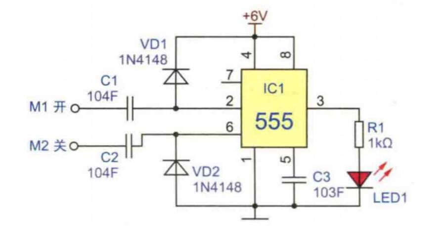
An electronic switch controlled by touch can be used to control the light on and off. The touch switch circuit is composed of IC five to five, rectifier diodes, LEDs, resistors and capacitors. IC1 and C1, C2, etc. form a bistable working mode. M1 and M2 are touch metal pieces, M1 is used to turn on the light, and M2 is used to turn off the light. When M1 is touched by hand, the human body's induction signal is rectified by C1 and VD1, triggering IC1 to be set, and the third pin of IC1 outputs a high level to drive LED1 to light up. When M2 is touched, the induction signal of the human body is rectified by C2 and VD2, which triggers IC1 to reset, the third pin of IC1 outputs a low level, and LED1 goes out.
This circuit needs to rely on a certain amount of human body induction signals when touching the trigger circuit. If the environmental conditions are not ideal, such as high humidity, insufficient human body induction signal strength, etc., it may lead to insensitive touch flips.
Here is a simple and practical touch delay switch circuit, which has the characteristics of simplicity, low cost, and good performance, which is very suitable for enthusiasts to make by themselves. Circuit principle:
The delay switch circuit is shown in Figure D1--D1. SCR forms the main circuit of the switch, and BG1, BG2, etc. form the control circuit of the switch.
Normally, BG1 and BG2 are in the cut-off state, the SCR is blocked, and the light H is off. At this time, the 220V alternating current is rectified by D1--D4, and R3 and DW make the LED light up, which is used to indicate the switch position at night. At this time, the current flowing through H is only about 2mA, which is not enough to make the lamp H emit light. When you need to turn on the light, you only have to touch the electrode sheet M with your fingers. Because the human body leakage current is injected into the base of BG2 through R5 and R6, BG2 is quickly turned on. The collector of BG2 is at low level, and BG1 is also turned on. Therefore, a trigger current is injected into the control electrode of SCR through BG1 to turn on SCR, and light H is energized and glows. At the moment when BG2 is turned on, C1 is connected in parallel to both ends of DW through the ce poles of BG2, so it is quickly charged with a voltage of about 12V. After the lamp is lit, the human hand leaves M. Although BG2 resumes the cut-off state, the charge stored in C1 is discharged to the BG1 emission junction through R1, so that BG1 remains in the on state, so the lamp continues to light. When the charge of C1 is basically discharged, BG1 resumes the cut-off state, and the SCR loses the trigger current. When the alternating current crosses zero, the SCR turns off and the light goes out.
The switching delay time is mainly determined by the values of resistors R1, R2 and capacitor C1. A set of experimental data is provided below for your reference. If you want to further increase the delay time, you can increase the C1 capacity. In addition to the above main factors, the BG1 magnification and SCR trigger sensitivity also affect the delay time.

The following figure is a simple analog touch shape circuit using the switching characteristics of a transistor.
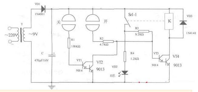
When the power is turned on, VTl-VT4 are all in the cut-off state, no current flows through the relay coil, the normally open contact of the relay is disconnected, and the light-emitting diode VD2 does not light up. When the "on" switch is touched with a finger, the power supply is injected into the base of VT3 through finger resistance (approximately several hundred to several thousand ohms), R2 is injected into the base of VT3, the composite tubes VT3 and VT4 are turned on, current flows through the relay coil, and the normally open contact is closed , VD2 lights up. Because the normally open switch is closed, R3 is connected to the VT3 base circuit. After the finger leaves the electrode, VT3 and VT4 can still maintain the conduction state. When it needs to be extinguished, you can touch the "off" electrode sheet. Because the positive power is injected into the base of VT1 through finger resistance and Rl, VT1 and VT2 are turned on, and the collector potential of VT1 and VT2 drops.
That is, the base potential of VT3 drops, VT3 and VT4 turn from the on state to the off state, no current flows in the relay coil, the normally open contact is disconnected, and VD2 is extinguished.
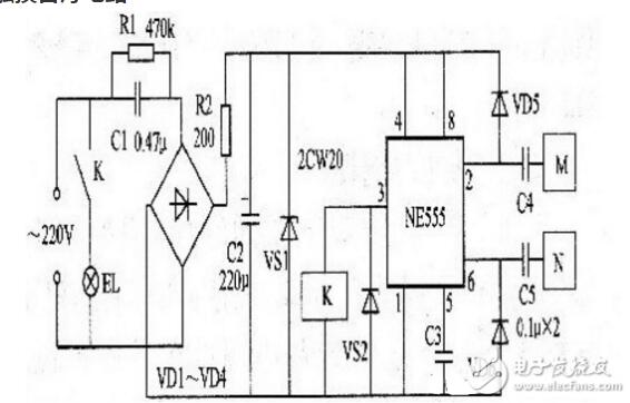
Simple touch switch schematic diagram (3)When the M electrode is touched, the clutter signal induced by the human body is coupled into the circuit via the capacitor C4. After being rectified by the VD5, the IC pin 2 gets a negative voltage, and the pin 3 outputs a high level. The relay K pulls in, and its contact is closed. When the lamp is powered on, the lamp is on; when the N electrode is touched, the clutter signal induced by the human body is rectified by VD6, so pin 6 gets a positive voltage, pin 3 outputs low level, relay Κ is released, and its contact disconnects the lamp power circuit , The lamp does not light up.
The above is the Simple touch switch schematic diagram we have listed for you. You can submit the following form to obtain more industry information we provide for you.
You can visit our website or contact us, and we will provide the latest consultation and solutions
Send Inquiry
Most Popular
lastest New
Send Inquiry
Privacy statement: Your privacy is very important to Us. Our company promises not to disclose your personal information to any external company with out your explicit permission.
Fill in more information so that we can get in touch with you faster
Privacy statement: Your privacy is very important to Us. Our company promises not to disclose your personal information to any external company with out your explicit permission.